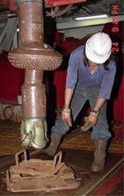
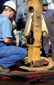
Drilling From the JOIDES Resolution Continued
Heave Compensation
It is a challenge to control the depth of drilling without the riser as a reference. The sea floor might be 3–4 km (1.9–2.5 mi) below the surface of the sea, and the ship could be rising and falling as much as 5 or 6 meters (16-20 ft) on waves at the surface. This movement, called heave, makes it difficult to keep the bit at the bottom of the borehole. Each time a wave raises the ship, the ship pulls upward on the drilling system. Steady pressure is essential so that drilling goes well and nothing gets broken. In riserless drilling, consistent weight is kept on the drill bit by a device called a heave compensator.
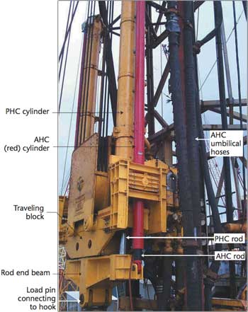
The heave compensator on the JOIDES Resolution consists of two systems: passive and active. Both are located within the derrick.
The Passive Heave Compensator (PHC) detects when the ship is moving up and down. It uses a large air cushion to try to keep the motion from affecting the drill string. The PHC has to overcome friction every time the ship goes up or down. Depending upon the amount of heave, the friction can cause a significant loss of efficiency.
|
Photo courtesy of IODP. |
The Active Heave Compensator (AHC) helps overcome friction created by the PHC. It measures the motion of the ship and compensates by adjusting a set of hydraulic rams from which the drill pipe is suspended. Changes in position add or remove slack in the drill string as needed. The AHC also maintains consistent weight on the bit so the bit stays in place even while the ship is moving.
The capacity of the heave compensator determines the maximum amount of force it can produce to support the suspended drilling rig and overcome the friction resulting from the sliding movement of the rams. The heave compensator enables the JOIDES Resolution to work in waves as high as 4 meters (13 ft). Without it, drilling could be done only when the seas were very calm.
Dynamic Positioning
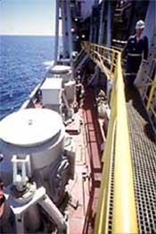 Computer-controlled thrusters help keep the ship stationary in heavy seas. |
In addition to dealing with heave, there is also the challenge of keeping the ship in place on the surface above the drill site, in spite of wind and currents. Usually the sea is far too deep to use an anchor. If the JOIDES Resolution were to drift sideways during drilling, it would pull the drillpipe sideways and snap it in two! In order for drilling to be successful and measurements to be accurate, the JOIDES Resolution absolutely must stay in the same horizontal position relative to the sea floor. A dynamic positioning system makes it possible for her to remain in place, even during drilling.
When the JOIDES Resolution is in position over the drill site, a device called an acoustic transponder is placed on the ocean floor. Sonar signals are sent to the transponder from the ship. It responds with its own sonar signals that are read by three sensors on the ship’s hull. A sophisticated computer system uses these signals to figure out the ship’s position and directs twelve thrusters to work as needed to keep her in place. Adjustments made by the thrusters enable the JOIDES Resolution to hold her position within 2% of the depth of the water beneath her.
|
Photos courtesy of IODP. |
||
|
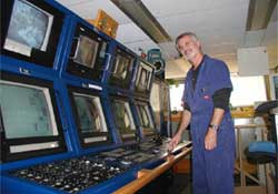
The dynamic positioning operator in is charge of keeping the ship in place over the borehole. |
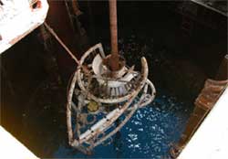
The subsea camera and sonar system is lowered through the moonpool to locate the borehole on the seafloor. When it has done so, the dynamic positioning system will be used to move the ship directly over the borehole. |
|
Wireline Logging
|
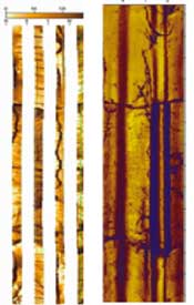
Image courtesy of USGS. Images of the same depth interval taken by the Formation Micro-Scanner (FMS) and Borehole Televiewer tools. |
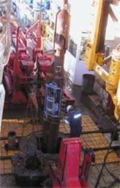 Photo courtesy of IODP. Logging tools being lowered through the rig floor. The large rust-colored tube carries an entire seafloor observatory system into the borehole. The silver metal pieces are pressure data loggers. |
Specialized equipment is used to log (record) measurements and other data from the borehole after drilling.
Sometimes tools are needed that cannot be used during the drilling process. In these cases, the bit is removed, and wireline logging tools are lowered on thin steel cables through the pipe directly into the borehole. Even though the pipes are comparatively large, to allow for coring, the tools cannot be more than 9.65 cm (3.8 in) wide in order to allow passage.
Wireline logging tools measure and record information from the surrounding rock, such as physical and chemical properties, structure, etc. Particularly effective is the Schlumberger Formation Micro-Scanner* tool, which creates images much like taking a picture of the inside of the borehole. The images can be used to identify geological structures and to locate fractures. They are also useful for showing exactly where a particular core sample came from. Because the standard Formation Micro-Scanner tool is too large to use on this project. In this case, a specially adapted smaller version of the tool has been designed, which just fits into the borehole!
The standard Formation Micro-Scanner tool measures over 11.43 cm (4.5 in) in diameter, so it is too large to use on this project. In this case, a specially adapted smaller version of the tool has been designed. At 9.525 cm (3.75 in) wide, it just fits into the pipe!
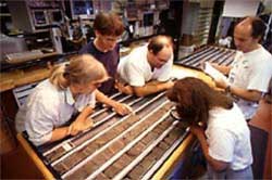 Photo courtesy of IODP. Scientists studying core samples on board the JOIDES Resolution |
Typically logging tools are joined together in tool strings to allow several measurements to be made at the same time. Various combinations of tools are used for different purposes. Each tool string is attached to a wireline cable and lowered to the bottom of the borehole. The logging measurements are taken when it is pulled back up the well. It is easier to keep constant tension on the somewhat stretchy cable while it is being pulled up. Sometimes, however, if the temperature in the borehole is too cold for the instruments to function well, the data is gathered on the way down. The trick is to get the data before the temperature affects the tools. If possible, the measurements are taken a second time on the way out.
|
An 18.5-inch drill bit. |
|
The “under reamer” drill bit can drill a hole larger than the diameter of the pipe through which it was passed. Photos courtesy of IODP. |
A wireline heave compensator counters the effect of the ship’s heave on the position and motion of the tool string. Most data is gathered continually, even while the tools are moving. Sometimes it is necessary to stop in order to take a certain measurement. The entire process may be repeated to improve accuracy, as well as to be sure that everything has been covered.
Later, when the core samples are examined and analyzed, information from the wireline logs adds to and confirms the findings. If a core has been damaged or is incomplete, the logs often provide missing information. If no core sample was taken at a particular location, the only data about that area may be recorded in the log.
Specialized Equipment
The JOIDES Resolution takes core samples while working in a variety of conditions, from the depth of the water to the composition of the seafloor. The goal is to get core samples in the best possible condition. A drilling technique that is highly successful in one location may not be suitable for another. For example, a rotating drill would destroy soft sediment, but a drill suited for soft sediment might not penetrate hard rock. The seafloor may have both hard and soft layers. Different situations require different drilling techniques. New procedures and equipment are constantly being developed.
In one method of drilling into a soft layer of rock, water pressure drives a coring tool through the drill bit and into the rock. If the rock contains hard and soft layers, an extended core barrel pushes into the soft layer. When it hits a harder layer, it retracts inside the drill bit. Until recently, it was not possible to drill into bare rock because a layer of sediment was needed to hold the drill string in position. Now, there is a way to get around this problem, by lowering a cement-filled guide base weighing 18,000 kg (19.84 tons) onto the ocean floor. The guide base stabilizes the drill string so that drilling can take place.
In some situations, specially designed drilling motors rotate the bit, but the main drill string does not turn. This method is useful in situations where vibration and fatigue from drilling can cause the core sample to crumble.
Another technique for drilling into fractured rock uses a water hammer—like a jackhammer except that it is powered by water—to create a 375 mm (14.8 in) borehole into the rock. Then it drives a 340 mm (13.4 in) casing into the borehole. The casing stabilizes the borehole as it is drilled.
*Mark of Schlumberger
Drilling Topics
 |
Riserless Drilling The Drilling Process |
 |
Heave Compensation Dynamic Positioning Wireline Logging |
 |
Specialized Equipment Drilling in Extreme Environments Determining Accurate Depths |
This content has been re-published with permission from SEED. Copyright © 2026 Schlumberger Excellence in Education Development (SEED), Inc.


